A Step-by-Step Approach
If you’re a newbie to hydraulics & hydrology then you’re in a good place right now. This blog is about how to design a detention pond outlet device without pulling your hair out. I can tell you first-hand, there are a lot of moving parts to a detention pond. Not just the pond itself but the devices that allow water to flow out of the pond.
If you’ve ever had the task of designing one then you’re at least familiar with standard design criteria that usually goes something like this: The storage facility must be designed to detain the post-developed flows to that of the pre-developed flows for the 2-, 10- and 100-year return periods.
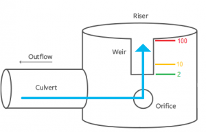
Simple enough. And, in all likely hood, the resulting outlet structure will look something like this:
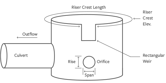
This is known as a “Multi-Stage” structure. Multi-Stage refers to the multiple stages or depths in the pond that this structure must address. In our case depths corresponding to the 2, 10, and 100 year runoff events.
You typically see as many devices in a multi-stage outlet structure as there events. In the figure above there are three. An Orifice, a Rectangular Weir and a Culvert. As for the Riser, well, it’s just there to hold the first two guys… Orifice and Rectangular Weir while conveying their flows to the culvert.
Since this article is more about the outlet structure design “procedure”, I won’t go into a lot of detail about the storage part or the actual storage-indication method calculations. But it’s important that you get this first step right. Ninety-nine percent of pond design failures are due to not having enough storage.
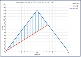
So let’s assume you already have done the storage estimating by developing the pre- and post-developed hydrographs. And then estimating the required storage by computing the area between the two as shown in the blue cross-hatched section above. Be conservative, you can always scale the pond size back. I just want to make sure you at least get a solution on your first try.
So Where Does One Begin?
You have several outflow devices, which one do you size first? The riser? Intuitively one wants to start with the orifice, then the secondary weir, then the riser and finally the culvert. In other words, you naturally want to design in the order of return periods, i.e., 2-yr, 10-yr and then 100-yr. Don’t do this! You could be at it all afternoon. The size of one affects the ability of the other, which affects another, and so on.
A Better Detention Pond Design Procedure
Here’s the secret to a no-fail pond outlet structure design:
Design your devices starting downstream and work your way upstream.
Not the other way around. Not by return period. Starting at the most downstream end, add a device at a best-guess size, location, slope, etc. Then perform a trial routing to determine if that device is sized to meet its criteria. If not, make adjustments until it does.
The next step is to add another device, just upstream of the previous one, with its invert elevation equal to the maximum stage reached during the previous trial routing. Perform a new trial routing to determine if that device is sized to meet its criteria. If not, repeat until it does. Continue this process of adding new devices until all event criteria have been met.
This is a simple and worthy procedure… unless you start with the wrong device. In which case you could end up chasing your tail. So let’s get started.
Size the Culvert First
Always begin your pond design by adding the Culvert. It is the most downstream device. Using the general procedure described above, try to size the Culvert to meet or exceed the upper end of your target outflows. In this case, the 100-year frequency.
When using standard, commercially available sizes however, you may not be able to size it perfectly. For example, an 18-inch circular pipe may allow too much discharge, but the next size down, 15-inch, may not allow enough, causing your storage pond to breach. You’re forced to accept the 18-inch. That’s perfectly okay. When this happens, just plan on using secondary structures (preferably a weir) to satisfy this upper end. The culvert is simply facilitating a way for water to exit the pond. It rarely is a flow-controlling device.
Next, Add the Orifice
The next upstream structure is the orifice. In this case, the 2-year event is up to bat. (Orifices seem to work the best in these cases as they have a somewhat linear stage-discharge curve and unlike weirs, are more predictable under large heads.)
At this point you can add a Riser structure but only as a container for the secondary structures. Set its crest elevation high for now. Almost to the top of the pond.
Set the orifice at, or just above, the bottom of the pond. (Note: If you’re using Hydrology Studio, be sure to check ON the multi-stage (“Flows through Culvert”) option.
Pick a size and perform a trial routing and observe. Adjust the size of the orifice until you’re satisfied with the maximum discharge, i.e., 2-year Target Q. When that’s done, make a note of the corresponding maximum water surface elevation from that routing. Now move upstream to the next device.
Add the Secondary Weir Structure
Here you have a choice of adding a weir or even another orifice. I prefer to use rectangular weirs but you should feel free to experiment with orifices as well. V-notch weirs can be difficult to get dialed in. Leave those for the researchers.
In this example we’re using a rectangular weir. Set its crest elevation to the maximum elevation reached in the orifice design. Next, set a best-guess crest length and do a trial routing. Per the general procedure, adjust the crest length, not the crest invert, and perform trial routings until you achieve the 10-year Target Q.
In most cases, this device will also satisfy the remaining, and intermediate, target discharge requirement(s). In our case the 100-year. If not, repeat this same step with an additional weir. (Basically turning it into a compound rectangular weir.) Simplicity should rule. One device is the better solution.
Don’t Be Tempted
You may be inclined at this point to use a Riser to satisfy that last criteria but I don’t recommend it. First of all, the riser crest will need to be large relative to the what you really need. After all, it’s holding the orifice and secondary weir(s) while attaching itself to the upstream end of the culvert. Its crest length could very easily surpass 12 feet when you need only one foot. The crest elevation then becomes very sensitive to changes to head. Remember, weirs are very powerful and can allow a lot of water to pass with a very shallow head. Think down the road when this pond becomes silted up, causing the maximum water surface elevation to rise slightly higher than designed.
However, there will be cases when you don’t have an economical alternative other than to use the Riser’s crest. Remember to subtract any other secondary weir crest lengths from the riser’s crest length, so you’re not double-dipping.
Add the Riser
Now you can add the riser. I like to add the riser last but honestly, you could have added it first, or whenever, but you don’t know where to set its crest elevation until the other structures have been set. You’ll end up moving it up and down a lot during the process, wasting time. If you insist on adding it earlier, set its crest high, but not above the top of the pond, and adjust those parameters last.
Size the riser for practical reasons and not so much for hydraulics. Set its crest above the final maximum water surface elevation reached during the last structure design. Set the crest length just large enough to hold the multi-stage devices as well as connect adequately to the upstream end of the culvert. Perform a final trial routing to insure it is not hindering the performance of the other structures. If it is, enlarge the crest length.
Done
Hopefully this post has given you some insight and guidance on how to approach your next detention pond design. The procedure should help save you some time and frustration regardless of what hydrology software you’re using. For more information on detention pond design software check out Hydrology Studio. Hydrology Studio’s Help contains a tutorial on how to use its Trial Routing feature which follows this same procedure.
More Detention Pond Design Examples
My First Pre/Post Development Project is a step-by-step article that walks you through a complete NRCS detention pond design using the exact procedure described above.
The Rational Method vs. NRCS Method is a must-read article that compares these two methodologies. The results may surprise you.
This step-by-step article describes how we designed a detention pond using the Modified Rational Method Step-by-Step and the procedure described above.
You can also see this process in action. Watch this video tutorial, Detention Pond Design in 3 Easy Steps.