Occasionally you will be faced with the question, “Should I use an Interconnected Pond analysis for this?” To my surprise, many of our users answer, “Yes” when they should be answering “No”.
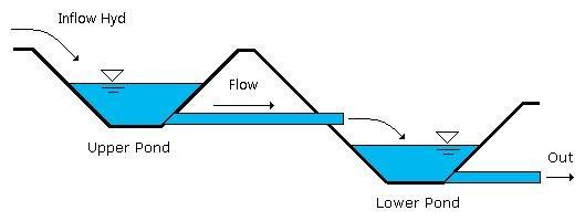
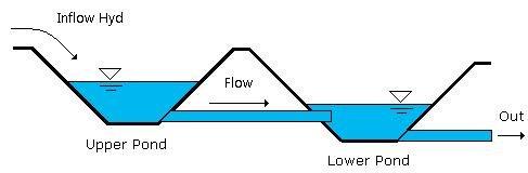
Interconnected ponds are two or more detention ponds that are hydraulically connected to each other. There’s typically an upper or upstream pond whose outflows are directed into a connecting lower pond. The lower pond’s outflows continue downstream as shown in Figure 1.
This is the simplest scenario and one that does not require an “Interconnected Pond” routing. And that is the topic of this blog post. When and when not to use this type of analysis.
In a nutshell, any time the lower pond’s water surface elevation reaches a level that creates a tailwater against the outlet devices of a connected upstream pond, you should use the Interconnected Pond routing function. A scenario like this requires a recalculation of the upper pond’s stage-discharge curve at each and every time step during the routing, resulting in thousands of extra calculations. So why go through all the trouble when you don’t need to?
When Not to Use Interconnected Pond Routing
The two ponds as situated in Figure 1 are independent of each other. The water surfaces shown represent their maximum. Notice that the water level in the lower pond stays below the invert of the upper pond’s outlet structure. It has absolutely no affect on the upper pond in that it does not create a tailwater against its outlet culvert. In this case the upper pond has no clue that a lower pond exists. The proper way to model this is to perform two separate pond routings. One for each pond. The outflow hydrograph from the upper pond should be used as the inflow hydrograph for the lower pond. You’ll have two individual pond route icons on your basin model when you’re done. A similar scenario is shown in Figure 2. Its outlet device is a weir rather than a culvert.
Again, two separate routings because the lower pond does not create a tailwater against the upper pond.
This is When to Use Interconnected Pond Routing
Any time the lower pond affects the upper pond, use an Interconnected Pond routing function.
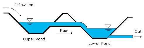
As shown in Figure 3, The lower pond’s water surface rises above the upper pond’s outlet device invert affecting the stage-discharge relationship of the upper pond. This in turn will affect the outflow hydrograph from the upper pond.
The routing process is accomplished by dynamically linking the two ponds together. The routing calculation procedure is done in single time increments (equal to the project Time Interval, for example 1 minute). During this procedure, the outflow from the upper pond, over one time increment, is in turn routed through the lower pond. The computed stage in the lower pond is then used as a tailwater for the upper pond for the next calculation increment. Its stage-discharge curve is recomputed. A new outflow is computed from the upper pond and the process is repeated for the remaining time increments.
How to Really Know
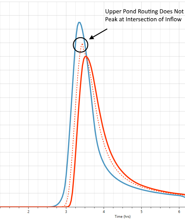
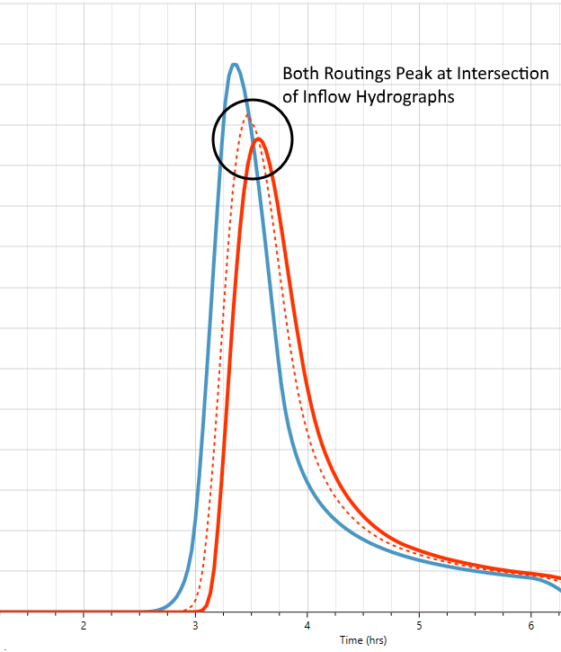
The resulting hydrograph routing charts will tell you whether or not an interconnected pond routing was needed. When an interconnected pond routing was required, you’ll notice that the upper pond routing hydrograph does not peak where it intersects the inflow hydrograph, like normal pond routings do. When both upper and lower hydrographs intersect their inflow hydrographs, it’s a tell-tale sign that an interconnected routing was not required.